Injection mold production (6/17/19)
We’ve made an order of an initial batch of 96 circuit boards and now it’s time to focus on the enclosures that will house the final circuit.
We recently submitted our enclosure design to the tooling company who will produce the mold. We only submitted the enclosure for now. The button that goes with it will be 3d printed for the prototyping stage and will be injection molded when we get additional funds from our crowdfunding campaign.
As a first step of the process they ran our part models through a series of ‘Design for Manufacturing’ (DFM) checks, which a manufacturer performs to check whether manufacturing will go smoothly. We went through this before for the original Signet case but we had the help of a consulting firm that had produced injection molded plastic parts in the past. Luckily we did a fair bit of research and had taken notes from the first time and were able to get our model to pass DFM with only a few small changes. An aspect of performing the DFM checks is to make an initial pass at designing the mold tool itself. The image below shows how the mold tool will function:
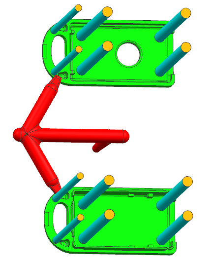
Both halves of the enclosure will be produced in the same mold. The red areas are channels called runners where liquid plastic will flow into the enclosure cavity areas. The areas where these channels meet the part cavities are called gates. In most cases the part will still be attached to the runners via the gate and will have be to snipped off with flush cutters. It was very important to us that this gate area not be on the outside of the case so that the outside appearance would be smooth in all areas. A downside of this requirement is that since the part will never be cut off the gate perfectly cleanly it will probably be necessary for us to file away excess plastic so that the case snaps together tightly.
The blue cylinders represent the so called ‘ejector pins.’ These are pins which are flush with the cavity during molding that push the part off the mold after the plastic cools. Our design requires several of these pins to reliably push the part off.
Our part has undercuts to form the snaps that hold the sides of the enclosure together, which might have increased tooling/molding costs because many snap designs are molded using removable slides in the mold to create the snap’s overhang that are then removed once the part cools before ejecting the part. But because the undercuts are attached to the flexible rim of the enclosure the rim can simply bend around the undercuts as the pins push the part out.
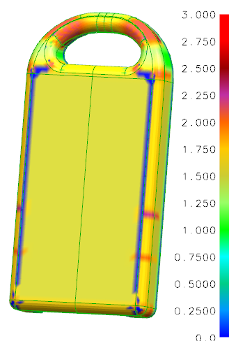
Other than coming up with a workable mold design the DFM checks looked for areas that might deform while cooling or prevent the part from ejecting. The main reason why a part might deform is if the thickness of the part is too uneven. This causes uneven cooling of the part which can change its final shape. The images below show the risk areas for our enclosure
| Outside thickness | Inside thickness |
|---|---|
 |
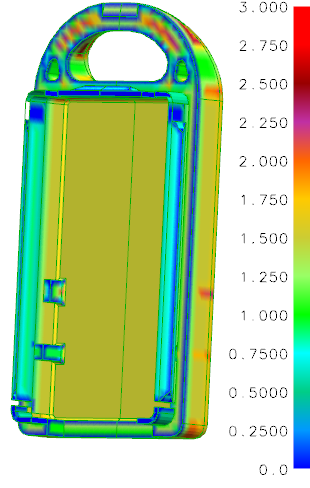 |
We were told that the thickest areas (shown in red) are of greatest concern, namely the keyring loop. We mitigated this risk by placing holes at the base of the keyring loop to reduce the thickness. We could have gone further and hollowed out the entire keyring loop but we decided we’d rather risk a cosmetic issue than make the keyring loop weak.
Making sure the part can come out of the mold is a matter of adding what are called draft angles. A draft angle is a change in the angle of a vertical surface so that it slightly faces the mold cavity. Large surfaces that are perfectly vertical tend to become attached to the mold and make the part difficult to eject. We were able to get away with very slight 1 degree draft angles since we have chosen a semi-polished surface finish which has less of a tendency to stick to the mold.
At this point we’re passing all DFM checks and the mold is currently being produced. We should have sample parts arrive shortly after the PCBA’s are completed, so in about a month.